Clipping Planes (Editor)
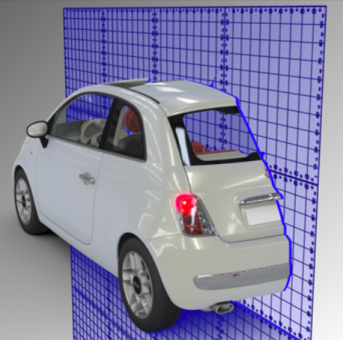
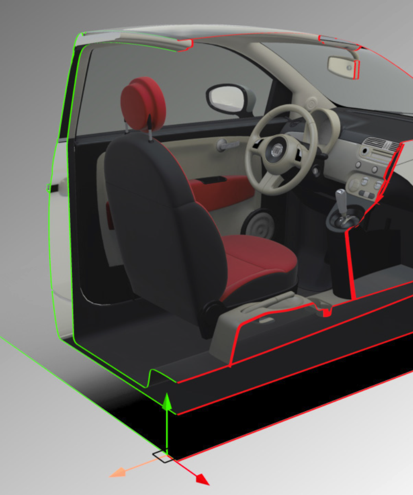
Clipping Planes is an editor that allows you to section the object of the scene in a pre-designated plane in order to see its interior.
The General Options zone provides render settings with the Face Elimination Policy function, which allows you to show or to hide the backfaces of the surfaces.
In the Face Elimination Policy drop-down list, the option Surfaces displays backfaces according to the settings provided in the Surface Properties in Shaper.
The Show Gizmo option displays a translation gizmo that can be manipulated to quickly move the plane of the active section.
The Tags section can be used to prevent surfaces from being clipped by the plane. Use the button to open a list of tags; select the tag that marks the surfaces that should not be clipped. Tags are assigned to surfaces using the Tag Manager in Shaper.
Patchwork 3D Design allows management and display of several Clipping planes simultaneously.
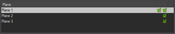
The Enabled function in the Clipping Plane zone must be checked in order to view the clipping plane in the active viewport.
The Clipping Plane zone provides the planar equation used to define the clipping plane. You can modify it by providing new numerical values.
You can also directly determine a cross-section plane in the Select the Plane zone:
- Select the desired cross-section plane in the drop-down list.
- Via the function Pick Plane, you can perform a cross-section starting with a plane directly selected in the active viewport, using the eyedropper tool, or alternatively a precise cross-section point by checking the Position option.

The contour of the clipped surface edges can be visually represented by enabling the Show option within the Contour zone.
You can choose a color for representing the cross section via the color chooser.
You can also modify the thickness of the line by entering a numerical value, or by using the up and down arrows of the keyboard.
Several options allow the display of sections to be optimized according to the requirements of the visualization.
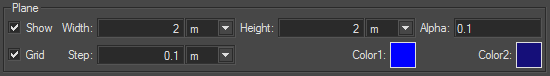
Thus the display of a plane can be activated (Plane zone > Show checkbox) and the value of its transparency (Alpha field), size (Width and Height fields), orientation, and color of its representation (Color1 and Color2) can all be modified. Alternatively, just a metric grid is displayed (Grid and Step options).